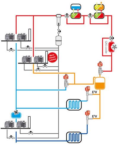
Transcritical cycle
Booster
|
In transcritical systems, CO2 is cooled but does not condense at the gas cooler outlet, being above critical temperature. A booster system is when there are two stages of compression of the same refrigerant, therefore the CO2 discharged by the low temperature compressors flows, via a intercooler, to the suction port of the medium temperature compressors. |
|
|
Transcritical CO2 booster systems are the most promising solutions for using natural refrigerants in retail contexts, above all in climates that are not too hot. They generally feature four sections with different pressures:
Different variants can be found on the market, above all using plate heat exchangers to increase system efficiency and/or assist correct operation. These are not normally part of system operating logic, and are not covered in this document. Advantages:
Critical:
|
|
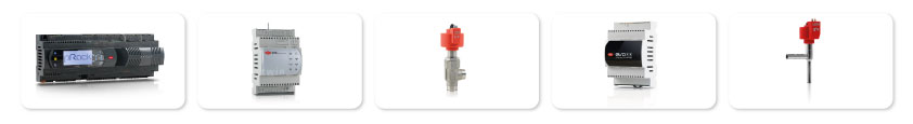
CAREL solution
- pRack pR300T + EVD: the compact Carel solution for complete control and management of CO2 compressor racks; the solution includes a driver for two-pole stepper motors to independently control two electronic expansion valves;
- E3V-C: the innovative series of valves for CO2 applications based on Carel's consolidated experience in the field of high-efficiency expansion valves, in particular for natural refrigerant systems;
- Ultracap:ensures complete closing of the valves (on the heat exchanger and showcases) even when there are sudden mains power failures;
- E2V-C: exploits the versatility and efficiency of the E2V valve while managing the high pressures involved; lower environmental impact combined with extra attention to energy saving.
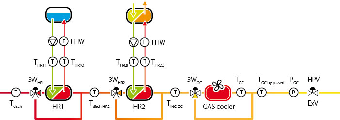
Heat recovery
|
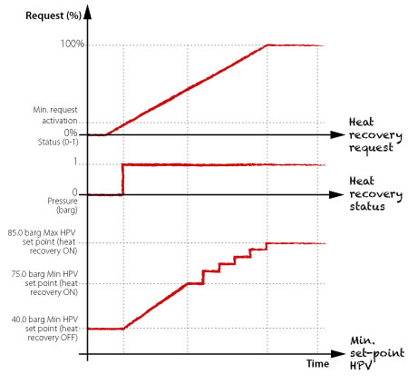
In a CO2 booster system, the heat recovery (or heat reclaim) function exploits the heat normally dissipated by the gas cooler for domestic hot water production or space heating. The controller designed for transcritical CO2 solutions (pRack pR300T) can manage two heat recovery functions at the same time (water or air). |
|
|
Each heat recovery function is activated and controlled based on the percentage of heat demand, which can be calculated based on:
An additional digital input can be used to preliminarily enable the function. Once activated, heat recovery can, if required, act on the high pressure valve set point and the effective gas cooler set point, either simultaneously (both at the same time) or sequentially, based on thresholds (first the high pressure valve and then the gas cooler, when exceeding a certain heat demand threshold). |
|
|
If acting on the high pressure valve set point, heat recovery has a direct effect on the lower limit for calculating the dynamic high pressure valve pressure control set point. The increase in this minimum set point means the system will operate in transcritical conditions even when the gas cooler outlet temperature is initially lower than the critical value, as typically occurs in the northern hemisphere in winter, the period when heat recovery is most needed. If the high pressure valve set point, calculated based on the gas cooler temperature, exceeds the minimum set point modified by the heat recovery function, the controller will use this newly calculated set point. |
|
|
If acting on the gas cooler set point, the gas cooler fan temperature set point can be gradually increased until reaching the maximum allowed limit. If the floating condensing function is enabled, i.e. the possibility to control the fans based on the outside temperature, this can be disabled when heat recovery is active. One final action to maximise heat recovery involves bypassing the gas cooler when the following conditions are true:
When these conditions are true, the bypass valve will start modulating according to the calculated bypassed gas cooler temperature set point, until totally bypassing the gas cooler when this temperature makes it possible. When heat recovery is deactivated, the HPV valve set point gradually returns to the calculated value in a set time. The same is true for the condensing temperature set point. |
|